Table of Contents
When optimizing lamination and form-fill-seal operations, it’s crucial that you assess stiffness upgrades for film and sheet; you can enhance web handling, avert sagging and wrinkling, and allow for greater line speeds without jeopardizing seals by opting for resins with a higher modulus, modifying the gauge, and using functional coatings or surface treatments. To determine the ideal combination for your application, you should evaluate the trade-offs among optics, sealability, and cost.
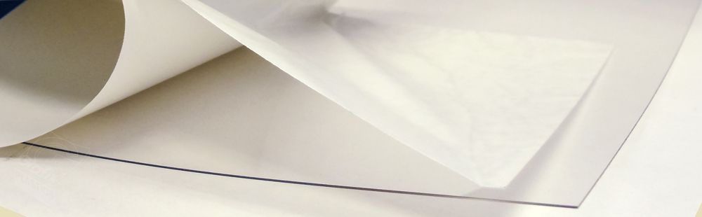
The Critical Role of Stiffness in Film Converting
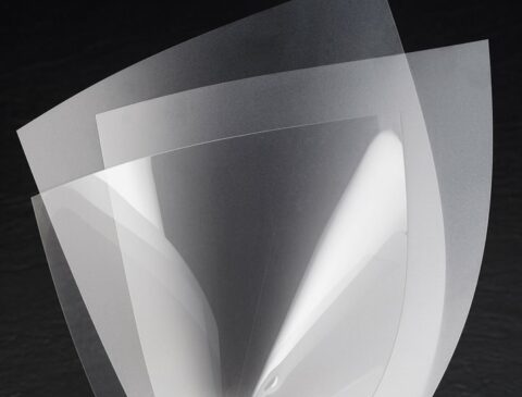
Stiffness governs web handling, register accuracy, and roll formation on lamination and form-fill-seal lines. At typical line speeds of 200–500 m/min, inadequate stiffness increases flutter, wrinkles, and misregisters that can raise scrap by 10–25% and force more frequent stoppages. You can target stiffness through layer composition or modulus adjustments to improve nip control, heat-seal consistency, and roll quality, allowing tighter tolerances and higher sustained speeds.
- Impact on Performance and Efficiency
Based on standard, increasing stiffness sharpens web tracking, reduces oscillation, and stabilizes tension profiles, cutting downtime and scrap. When you upgrade bending modulus or add a reinforcing layer by 20–30%, pilot runs have shown throughput gains of 10–20% and improved seal consistency, enabling line speeds to climb from 300 to 360 m/min. Better roll-build also shortens changeover time and reduces edge-trim loss.
- Applications Across Various Product Lines
Flexible food pouches, medical sachets, and industrial liners each require specific stiffness windows: 12–40 µm BOPP for tight print register and crisp peel, 25–80 µm PE blends for pillow bags, and 75–150 µm sheets for heavy-duty FFS. You’ll tune stiffness to balance machinability with end-use performance—firmer films for high-speed VFFS, softer constructions for reseal and cold-seal formats.
For example, confectionery lines at 300–350 m/min favor higher machine-direction stiffness and MD/CD ratios near 2:1 to prevent bag sag, while liquid-dairy pouches benefit from increased cross-direction stiffness to resist filling turbulence. You should also account for barrier layers—EVOH or metalized films add stiffness and often require nip-pressure and laminating-adhesive adjustments to avoid delamination during high-speed lamination.
Materials that Maximize Performance: Compatible Structures
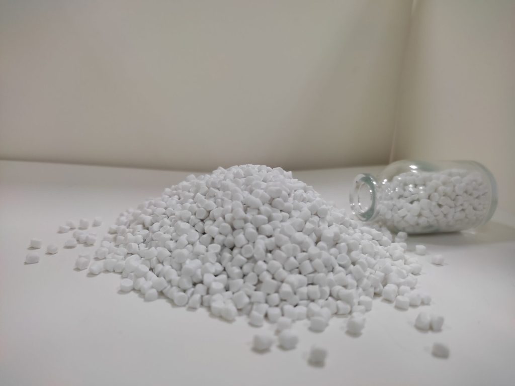
Pick film combos that crank up stiffness but don’t mess with sealability. Basically, slap a tough outer layer like BOPP or oriented PET on top of a chunkier, more flexible core—think cast PP or HDPE—and use adhesives that actually make sense for your setup. Bump up the outer layer thickness by, say, 5–15 microns, or swap out a 40-micron core for a beefier 60-micron high-modulus one. Boom: you’re looking at a solid 10–30% boost in layflat and machine-direction stiffness. Makes running those lamination and FFS lines way smoother, and you still keep your seals strong. Win-win, right?
- Leveraging PP Cast and BOPP Films
BOPP facings at 12–35 µm give you excellent tensile modulus and print clarity, ideal for high-barrier laminates, while cast PP at 20–60 µm adds damping and better cold-seal performance. Converters report that replacing a 20 µm BOPP face with a 25–30 µm cast PP in a 3-layer laminate reduced curl and improved cross-direction stiffness by roughly 15–20%, lowering web breaks on high-speed pouch lines.
- Exploring the Benefits of HDPE Films
HDPE films in the 40–100 µm range raise puncture resistance and bending stiffness in mono-PE and coextruded structures, helping you reduce edge-folding and improve vacuum retention during form-fill-seal. Field trials show using an 80 µm HDPE outer layer reduced film flutter and static-related web defects on FFS machines by about 15–25% compared with LDPE equivalents.
High crystallinity and density (≈0.94–0.97 g/cm³) give HDPE a flexural modulus typically between 700–1,400 MPa, which you can exploit to tune stiffness without adding exotic materials. Use tie layers (EVA, maleic-anhydride modified polyolefins) or corona treatment to bond HDPE to metallized or adhesive layers; specifying a coextruded HDPE skin often improves sealing window stability and abrasion resistance for harsh downstream handling.
Precision in Formulation: Dosing Guidelines to Minimize Haze
- Balancing Additives for Clarity and Stiffness
Target particulate antiblock at 0.2–0.6 wt% and slip agents at 0.3–1.0 wt% to limit light scattering while preserving hand-feel; add a nucleating agent at 0.02–0.2 wt% to raise biaxial stiffness by 5–12% without measurable haze increase. You can offset a 0.4% antiblock haze penalty by pushing nucleator from 0.05% to 0.12% and trimming slip by 0.1%, keeping total additive load below ~2 wt% for best clarity.
- Common Pitfalls in Dosing Practices
Overdosing particulate antiblocks (>0.8 wt%) or using particle sizes >5 μm often spikes haze by 20–40%; improper masterbatch dilution (poor carrier compatibility) causes agglomerates that scatter light; inconsistent feeder calibration and hopper segregation create lot-to-lot haze variability. You should aim for particle sizes <3 μm, confirm masterbatch concentration, and maintain feeder accuracy within ±0.5% of setpoint.
Implement routine QC: use laser haze meters (target final film haze <3%), optical microscopy to screen for agglomerates, and melt filtration checks. In extrusion, prefer twin-screw dispersion with specific energy tailored to your polymer—typical energy windows 50–150 kJ/kg—while dosing additives via a compatible masterbatch at 2–6% to achieve stable, repeatable active levels and avoid flash blooming or thermal degradation during temperature excursions.
Navigating Process Challenges: Slit, Wind, and Forming Behaviors
Honestly, when you start working with stiffer materials, everything gets weird fast—stuff just doesn’t behave like it used to. You can’t just keep running the same old recipes and hope for the best; you gotta work with your machines and tweak your settings. As the stiffness cranks up (we’re talking, like, 10 to 40 percent higher). So yeah, you’ll probably have to slow the line down, mess with the knife angle, and keep a way closer eye on how your rolls are stacking up.
If you want to keep things from going totally sideways, some classic moves are switching to anvil slitting (especially when you’re dealing with those beefy laminates), swapping out your mandrels for the chunky 76 mm (3-inch) cores so things don’t wobble, and capping your finished roll diameter at around 700–800 mm. Otherwise, boom—collapsed rolls, and nobody wants to deal with that mess.
- Understanding Slitting and Winding Dynamics
Stiffer webs increase radial stress at slit edges, producing burrs and micro-cracks unless you optimize knife clearance (typically 0.03–0.15 mm), select blade type (razor for thin films, shear for laminates), and reduce tension from, for example, 25 N to 10–15 N during slitting. You’ll also need to monitor roll build profiles with non-contact diameter sensors and apply differential winding across the face and back to prevent telescoping; case studies show differential tensions corrected 80% of telescoping events.
- Forming Behavior Adjustments in High-Stiffness Contexts
Stiffer stacks alter draw-down ratios and strain distribution, so you should increase tool radii and use plug-assist to reduce thinning—bump up fillet radii from 1.5 mm to 3 mm and cut forming depth by 10–20% for materials with 30–50% higher modulus. Preheating the web 30–80°C can lower apparent modulus during forming, and switching from male to female molds often reduces surface fracture on corners and hems.
Further adjustments include changing dwell times and lowering forming speeds: increasing dwell by 15–25% and halving speed in a trial can reveal whether strain concentration or elastic springback is limiting yield. You can instrument the tool with IR thermography and strain gauges to map failure zones; in one production trial converting from 20 µm PET to a 30 µm PET/PE laminate, targeted plug-assist and a 20% slower cycle eliminated 90% of corner tears while maintaining throughput with minor downstream speed compensation.
Weighing Sealability Against Puncture Resistance
You balance lap-seal strength (commonly 10–30 N/15 mm in FFS operations) against puncture resistance (often measured 500–3,000 gf) by tuning film structure and process parameters. Increasing stiffness with thicker PET or PLA layers raises modulus and flatness but reduces heat transfer to the sealant, so you may need higher dwell time, thicker sealant, or surface treatments to retain 12–25 N/15 mm lap seals without sacrificing puncture performance for sharp-cornered products.
- Trade-offs Between Seal Integrity and Mechanical Strength
Adding a 12–50 µm PET or PLA layer can boost stiffness 15–40% yet lowers sealability because of reduced thermal conductivity; you typically compensate by increasing PE sealant gauge by 5–10 µm or raising seal temperature 10–30°C. Tie layers (adhesives) and corona/plasma treatment often restore adhesion without large sealant increases, letting you keep mechanical strength while meeting seal strength targets in automated FFS lines.
- Innovative Solutions for Enhanced Performance
Selective spot lamination, micro-embossing, and co-extruded tie layers let you concentrate sealability where needed and preserve overall stiffness—spot lamination can maintain 10–30% stiffness gains while leaving continuous seal zones of optimized PE. Nanoclay or platelets in mid-layers increase puncture resistance with minimal gauge change, and thin high-modulus BOPET (8–12 µm) paired with a 6–12 µm PE sealant often hits both stiffness and seal targets.
In pilot trials, converters combined 12 µm BOPET + 20 µm oriented PLA with an 8 µm PE sealant and corona treatment to achieve roughly 10–18% higher bending stiffness while maintaining lap seals around 14–18 N/15 mm and stable puncture resistance for filled pouches. You can also deploy ultrasonic sealing to lower thermal load—reducing dwell by up to 50%—or laser scoring to create controlled tear paths that prevent accidental punctures without weakening the main seal.
Essential Test Methods for Evaluating Stiffness
Combine objective metrics to qualify stiffness upgrades: Gurley porosity, tensile modulus, cantilever/3‑point bend and dynamic mechanical analysis (DMA). You should run at least five replicates per condition, test samples after 48‑hour conditioning at 23°C/50% RH, and report modulus (MPa/GPa), elongation (%), and bending stiffness so you can correlate lab data with run‑line forming and FFS behavior.
Utilizing Gurley Tests for Porosity and Stiffness Measurement
Gurley measures air flow as seconds per 100 mL and helps you distinguish dense films (<10 s) from microporous structures (100–1,000+ s); porosity often correlates with low bending stiffness and higher compressibility. Use Gurley in tandem with thickness and basis weight to predict handling: two films with identical basis weight but 10× difference in Gurley will behave very differently on feed rollers and in lamination tack.
Assessing Tensile Modulus and Bending Properties
Measure tensile modulus (ASTM D882 style protocols) to quantify stiffness: oriented PET/BOPP typically sit around 3,000–4,000 MPa, HDPE ~800–1,200 MPa, LDPE ~200–400 MPa. Expect bending stiffness to scale with thickness^3, so doubling film thickness raises bending rigidity roughly 8×; you can leverage this to tune runability without changing polymer chemistry.
Specify test conditions: use 50–200 mm/min strain rate and 50 mm gauge length as a baseline, condition samples 48 hours at 23°C/50% RH, and report secant modulus at 1% and 2% strain for forming-relevant stiffness. Apply DMA to capture storage modulus across 20–120°C to predict behavior at seal-bar temperatures; check laminated samples too, since adhesives can increase effective modulus by 10–60% depending on layer thickness and cure.
Ensuring Longevity: Print and Laminate Adhesion Assessment
You should verify adhesion using 180° peel tests at 300 mm/min and target 2–8 N/25mm depending on substrate; measure surface energy with Dyne pens aiming for 38–52 dynes/cm on treated polyolefins; monitor lamination nip temperature (typically 80–150°C), pressure and dwell to avoid squeeze-out; run accelerated aging at 70°C for 72 h and cyclic flex tests to confirm performance over intended 12–24 month shelf life.
- Critical Factors in Adhesion Performance
You must track these variables that most directly change bond strength:
- Substrate surface energy and treatment level (corona/plasma; 38–52 dynes/cm)
- Ink chemistry and full cure/dry profile (UV vs solvent; solvent retention)
- Adhesive type, coat weight and tack (EVA, PO, solventless; 1–5 g/m²)
- Lamination parameters: temp (°C), nip pressure (bar), line speed (m/min)
- Contamination, storage humidity and release-agent residues
The interplay of these factors sets both initial peel and after-aging retention.
- Methodologies for Testing and Improvement
You should combine standardized tests (ASTM D3330 180° peel, ASTM D1876 T‑peel, shear tests) with quick QC checks (cross‑hatch tape per ASTM D3359, solvent rub). For improvements, trial primers such as maleic‑anhydride grafted polyolefins, raise corona treatment above ~40 dynes, or switch adhesive chemistries; validate each change with conditioned peel and 70°C/72 h aging plus flex cycling.
In practice, prepare samples conditioned at 23°C/50% RH, run 180° peel at 300 mm/min on at least five replicates, report mean and SD, then age matching laminates at 70°C for 72–168 h to uncover latent failures; if peel drops >25% after aging, test mitigation: increase corona in 5–10 dyne steps, add a 1–3 g/m² tie‑layer (EAA or grafted PO), or raise nip pressure 10–50% while monitoring seal integrity—in trials, raising corona from ~30 to ~45 dynes often converted marginal bonds (≈1–2 N/25mm) to robust bonds (>3–5 N/25mm), proving the value of systematic, metric‑driven adjustments.
Sustainability in Focus: Recycle Stream Considerations
Your stiffness upgrades directly change how films behave in recovery systems: adding PET or metallized layers can sink in float-sink separation, while EVOH or PVdC barriers interrupt melt-flow and extrusion. Aim for mono-PE/PP constructions when possible, align with APR and How2Recycle guidance, and validate performance with real recycling trials to avoid creating non-recyclable fractions that force material to energy recovery or landfill.
- Assessing Impact on Recycling Processes
Run targeted audits and lab trials you design to quantify impacts: perform density separation, sink-float tests, and extrusion trials to observe gel formation, discoloration, or MFR shifts. Use FTIR mapping to detect barrier residues and coordinate with reclaimers to establish acceptable contamination thresholds and process tweaks—such as changed wash temperatures or filtration—to maintain throughput on existing PE/PP film lines.
- Innovations for Better Recyclability
Prioritize mono-polymer laminates, peelable sealants, and water-dispersible tie-layers that let you retain stiffness while keeping recyclability; several brands moved pouches from multi-material to mono-PE to meet 2025/2030 circularity targets. Explore emerging barrier coatings that are removable during recycling and label solutions like How2Recycle store-drop-off to recover film at retail collection points.
Chemical and enzymatic recycling provide fallback routes when mono-material design isn’t feasible: chemical depolymerization (methanolysis/glycolysis) converts PET back to monomers for repolymerization, while enzymatic processes (e.g., industrial pilots targeting PET) can handle mixed or contaminated streams more effectively than mechanical recycling. Pyrolysis and solvent-based dissolution treatments are scaling commercially to convert mixed polyolefins into feedstock for new polymers; you should model total cost, carbon footprint, and logistics against expected volumes before specifying these as end-of-life solutions.
Summing up
Just a heads-up—if you’re beefing up the stiffness on your film or sheet for lamination or form-fill-seal, don’t just slap on a thicker material and call it a day. You gotta actually check the modulus, the thickness, whether the coatings play nice, and if your machines can even handle the new setup without throwing a fit. Stiffer isn’t always better if it turns your line into a jam-fest or messes with your seals. Test it out, tweak your tension, mess with the nip, play around with your sealing temps—basically, expect to babysit the process until it runs smooth. Oh, and make sure the product inside actually survives all this tinkering. It’s a balancing act, for real.