Table of Contents
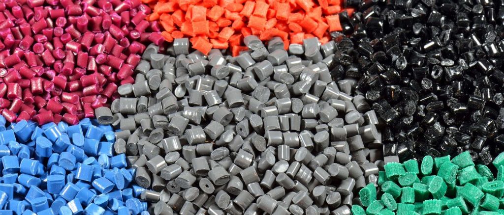
There’s a clear set of PP/PE design rules you should follow when using stiffening additive masterbatch to maintain manufacturability and performance. The global market for plastics (PE, PP, PU, PVC, PET, and PS) was valued at USD 624.8 billion in 2023 and is expected to increase at a compound annual growth rate (CAGR) of 4.2% from 2024 to 2030, reaching USD 645.1 billion.
Increase nominal wall thickness slightly, soften sharp corners with generous radii, avoid deep narrow ribs and instead use tapered rounded ribs to reduce stress concentrations, design bosses and snap features with adequate fillets and draft, control gate placement and cooling to minimize warpage, and account for reduced elongation and impact resistance in your tolerances.
Transformative Effects of Stiffening Additive Masterbatch

You’ll see stiffness gains translate directly into part redesign opportunities: typical dosing (2–6 wt%) raises tensile/flexural modulus 20–60% in PP/PE, enabling 10–30% wall reductions on caps and crates while keeping rigidity. Faster crystallization can cut cycle time 5–25% but also alters orientation and MFI (often a 10–40% drop), so adjust gate size, melt temp (PP 200–230°C), and injection pressure accordingly.
- Unpacking Modulus Increases and Their Implications
Higher modulus lets you trim wall thickness and add longer unsupported spans: in practice a 30% modulus boost can permit ~15% thinner walls on screw caps, yet impact strength may fall 5–25% depending on phase morphology. You should re-evaluate rib fillets (increase radii by 10–30%), increase gate diameters slightly, and run tensile and drop tests after every 1 wt% change to catch brittle failure modes early.
- Navigating Shrinkage Anisotropy and Density Trade-Offs
Stiffening additives change nucleation and orientation: flow-direction shrinkage can drop by 0.1–0.5 percentage points while transverse shrinkage rises, producing ovality in thin-wall parts and ejection stresses in crates. Density shifts are small (±0.01–0.03 g/cm³) with mineral-filled masterbatches but can matter for weigh-sensitive caps; quantify shrinkage in-flow and transverse for each cavity to set pack and cooling strategy.
To manage anisotropy you’ll balance flow and solidification: increase pack pressure 10–30% and extend hold time 10–50% to reduce transverse voids, raise mold temperature by 10–30°C to promote uniform crystallization in thicker sections, or add flow restrictors to reduce orientation in critical thin-wall features. Use polarized light microscopy, micro-CT, and DSC to correlate orientation, crystallinity, and local density; iterate in 0.5–1 wt% steps to optimize stiffness without unacceptable toughness loss.
Choosing the Right Ingredients: Base Resin and Additive Selection
- Comparing PP Homopolymer, Random Copolymer, and HDPE
PP homopolymer delivers the highest stiffness (tensile modulus ≈1.3–1.6 GPa) and melting point (~160–170°C), making it your go-to for rigid caps and crates; PP random copolymer trades modest stiffness for better low‑temperature impact and surface finish, suited to thin‑wall caps and snap fits; HDPE offers higher density/crystallinity with modulus around 0.8–1.2 GPa and Tm ≈125–135°C, giving you excellent stress‑crack resistance for heavy‑duty crates and outdoor parts.
Resin Comparison
| Resin | Notes (Properties & Use) |
|---|---|
| PP Homopolymer | High stiffness (≈1.3–1.6 GPa), Tm 160–170°C, MFR 0.3–50 g/10min; best for rigid caps/crates and thin‑wall sections needing dimensional stability. |
| PP Random Copolymer | Improved low‑temp impact and clarity, slightly lower stiffness, Tm ~150–165°C; ideal for thin‑wall caps, consumer packaging, and cosmetic finishes. |
| HDPE | Higher crystallinity and density, modulus ≈0.8–1.2 GPa, Tm 125–135°C; excels in heavy crates, chemical resistance, and outdoor durability. |
- Optimizing Carrier Matches and Additive Combinations
Match the masterbatch carrier polymer to your base resin—use PP carriers for PP parts and PE carriers for HDPE—to avoid phase separation and surface defects; target carrier MFR within ±30% of the base resin to keep melt flow consistent; start trials at 1–5 wt% active additive (typical masterbatch at 10–20% loading) and monitor flexural modulus, impact, and processing torque.
Run a 3% active additive trial delivered by a 15% masterbatch (20 g/kg dosing) to gauge stiffness gains—many formulators report 15–30% modulus increases in crates with a matched PP carrier; for mixed PP/PE blends add 1–3% compatibilizer (maleic‑anhydride grafted PP/PE) to maintain dispersion; adjust barrel temps (PP 200–230°C, HDPE 180–220°C) and mold temps to balance cycle time versus crystallinity, and validate with DSC/DMTA and part‑level impact testing before scale‑up.
Designing for Strength: Wall Thickness and Coring Strategies
- Tailoring Wall Thickness for Different Part Types
It could said that target 1.2–2.0 mm for caps, 0.5–1.0 mm for thin‑wall consumer parts, and 3–6 mm for crate walls; ribs typically sit at 1.5–3 mm thick and 3–8 mm tall. Stiffening additive masterbatch often lets you reduce wall thickness by ~10–20% while keeping flexural modulus, but expect elongation at break to fall 15–30% at common loadings. Use transition radii ≥1.5× local thickness to lower stress concentration and avoid brittle failure.
- Caps: 1.2–2.0 mm, keep uniform sections and necks ≥1.2 mm.
- Thin‑wall parts: 0.5–1.0 mm, add 0.2–0.4 mm in high‑stress zones or under threads.
- Crates: 3–6 mm walls with ribs 1.5–3 mm thick for stacking and impact.
- Perceiving trade‑offs: cutting thickness ~15% saves material but can increase notch sensitivity and reduce impact strength by ~20%.
| Part Type | Recommended Thickness / Notes |
|---|---|
| Caps | 1.2–2.0 mm; uniform walls, radiused transitions |
| Thin‑wall Parts | 0.5–1.0 mm; reinforce high‑stress areas +0.2–0.4 mm |
| Crates & Panels | 3–6 mm; integrate ribs 1.5–3 mm thick, use ribs for stiffness |
| Ribs & Fillets | Ribs: 1.5–3 mm thick, fillet radii ≥1.5× wall thickness |
- Coring Techniques to Minimize Brittleness
You can core out thick solid sections to remove brittle center material while keeping a 0.7–1.2 mm solid skin that preserves impact performance; typical coreouts remove 30–50% of the cross‑sectional area. Favor tapered cores with fillets ≥0.5–1.0 mm to reduce sink and stress risers, and locate gates away from cored zones to ensure proper skin formation and packing.
Practical options include simple circular coreouts, honeycomb panels, gas‑assist or structural foam for larger parts, and microcellular foaming for thin sections. In crate panels you can core 40–50% of area to cut weight 15–25% while keeping bending stiffness if outer skins and ribs remain intact. Always validate with moldflow: cored geometries change cooling by 10–30%, so adjust packing, venting and annealing schedules to restore impact strength and avoid sink or voids.
Structural Enhancements: The Role of Ribs and Bosses
Ribs and bosses deliver targeted stiffness without blowing up part mass: adding a 1.0 mm rib to a 0.8 mm thin wall can raise local bending stiffness two- to fourfold. You should place ribs to support flat panels and tie into load paths, and locate bosses on thicker islands with chamfered transitions; for molded-fastener bosses size bases to roughly 2.5–3× the screw major diameter and provide 0.5–1.0 mm draft for demolding.
- Ideal Rib Dimensions and Spacing Guidelines
Design ribs at 0.4–0.6× the nominal wall thickness to avoid sink and voids; limit rib height to ≤3× wall thickness and keep the height-to-thickness ratio near 2–2.5:1. Space ribs at least 3× the rib height center-to-center to prevent warpage and allow flow; add a fillet radius at the rib base of 0.25–0.5× rib thickness and a 0.5–1° draft on sidewalls.
- Strength Considerations for Knit-Line Orientation
Knit (weld) lines in PP/PE can cut tensile strength roughly 20–50% depending on grade and processing, so you want to steer flow paths so knit lines fall in low-stress regions or along compressive features rather than across thin cantilevered webs. Favor gate locations that push the meeting point toward corners, bosses, or outside neutral bending axes to preserve load-bearing capacity.
Mitigation tactics you can apply include raising melt temperature 10–20°C and mold temperature 10–30°C to improve interfacial diffusion, increasing packing/hold time by ~10–20% for better fusion, or using sequential valve gates and flow leaders to control meeting lines. Local thickening or adding small chimneys/flow fingers near expected knit lines also helps; verify changes with short-run tensile tests and optical inspection of the weld line.
Engineering for Precision: Gate and Runner Design
Design gates and runners to compensate for the increased melt viscosity and stiffness from your additive by increasing gate area (0.8–1.5× nominal wall thickness) and using 3–6 mm runner diameters in cold systems or hot-runner manifolds to eliminate cold slugs. Favor valve or submarine gates on thin-walled caps to reduce shear and vestige, and use balanced runner layouts or gated drops every 80–120 mm on large crates to keep filling symmetrical and packing uniform.
- Strategic Gate Placement for Optimal Packing
Place gates closer to thick features and high-mass sections so packing feeds bulk areas first and avoids starving thin walls; for circular caps use central pin or fan gates, while long panels perform better with multiple edge or tab gates spaced evenly. Balance gate count and location to minimize flow length differences—symmetry every cavity or along the runner typically reduces knit lines and gives consistent crystallinity and shrinkage across your part.
- Techniques for Minimizing Orientation-Driven Warp
Reduce orientation by lowering shear and equalizing flow: enlarge gate/running area, slow initial injection velocity, and extend pack time so molecules can relax during pressure hold. Implement symmetric multi-gate layouts or sequential valve gating to control melt front direction, and design ribs to interrupt straight long flow paths; these measures cut anisotropic orientation and decrease post-mold warp on stiffened PP/PE parts.
For deeper control, use valve-gate sequencing to stage pack pressure—start with outer gates closed to fill inner bulk, then open peripheral gates for balanced packing—this can drop residual stress significantly. Combine that with mold temperature profiling and controlled cooling to slow skin solidification, plus modest reductions in melt temperature (5–15°C) and measured decreases in injection speed to lower shear-induced chain alignment for parts with tight flatness tolerances.
The Science of Cooling: Layout and Cycle Optimization
Cooling layout vs. cycle optimization
| Design/Location | Cooling & cycle rule |
|---|---|
| Conformal cooling near thin walls | Place channels 2–4 mm from cavity to cut cycle by 15–30% and reduce thermal gradients to ±2°C. |
| Thick ribs or bosses | Isolate with slower-flow channels or local chillers; increase local cooling time by 10–25% to avoid core shrink and sink. |
| Multi-cavity balance | Use equal-length circuits and flow restrictors; aim for <5% cycle time variance between cavities. |
| Gate and runner placement | Locate gates to promote uniform fill and pack; shorter runners reduce hold time and help thin-wall solidification. |
| Mold temperature control | Target 25–40°C for PP/PE thin-wall; monitor with multiple thermocouples spaced ≤50 mm for uniformity. |
- Ensuring Mold-Temperature Uniformity
You should maintain mold surface uniformity within ±2°C across the cavity by using multiple thermocouples, balancing water circuits, and adding insulation on non-critical faces; place sensor points at the thinnest, thickest, and farthest locations from the gate, verify with thermal imaging, and tune flow rates so inlet/outlet ∆T stays under 8°C to prevent uneven crystallization and localized warpage.
- Adjusting Cooling Times to Combat Distortion
Adjust cooling times to ensure skin and core reach target solidification before ejection: for 1.5–3.0 mm thin walls aim for skin freeze in 3–6 s and core temperature ~50–60°C at ejection, increasing cooling time locally by 10–30% around thick features or ribs to reduce differential shrink and curl.
Run short-run trials instrumented with part thermocouples and use Moldflow to correlate predicted centerline crystallization times with measured data; for parts with stiffening additive, you may need 15–25% longer hold/cooling than neat PP due to altered crystallization kinetics. Try step-cooling—rapid initial cooling to set the skin followed by reduced coolant temperature for core cooldown—or use sequential valve-gated cooling to prioritize thick sections without lengthening the overall cycle across thin areas.
Locking in Quality: Dimensional Stability and Tolerance Management
Define tolerances from validated shrink and warpage data rather than rules of thumb: aim for ±0.05–0.2 mm for high-precision caps, ±0.5–2.0 mm for crates, and ±0.1–0.4 mm for thin-wall components. Use masterbatch loading (2–12% mineral filler or 5–15% stiffening additive) to cut linear shrink and increase modulus; expect PP shrinkage to fall from ~1.5–2.5% unfilled to ~0.2–1.0% filled. Update CAD offsets per cavity and process window to lock in repeatable parts.
- Utilizing Shrink Data for Accurate Specifications
Collect shrink numbers under production cycle conditions—measure flow and transverse shrink on plaques and full cavities after standard cooling and 24–72 hour conditioning. Use those directional shrink values to size cavities and set tolerance stacks: for example, apply 1.8% flow shrink for unfilled PP or 0.6% for a 10% talc masterbatch in your X-axis offsets. Log shrink vs. mold temp, pack pressure, and part thickness to adjust specs for different tool sections.
- Targeting Flatness and Creep Resistance
Control warpage by balancing wall thickness, symmetric ribbing, and gate placement to minimize orientation-induced curl; target flatness under 0.3–0.5 mm for caps and <2 mm for large crates. Reduce long-term deformation by raising flexural modulus via 5–12% stiffening masterbatch and keeping sustained stresses below service limits; validate with accelerated creep tests (e.g., 1,000-hour at elevated temperature) and set acceptance criteria based on measured permanent set.
In one production example, a 350 g thin-wall crate improved planarity from 6 mm to 1.1 mm by adding 8% talc-based stiffener, moving the gate to a center-fed runner, and increasing mold temperature by 8 °C to reduce thermal gradients. You can further trim creep by specifying anneal cycles (e.g., 2–4 hours at 70–90 °C for PP), optimizing pack time to reduce residual stress, and specifying maximum long-term stress—derived from ASTM/ISO creep data—so parts meet flatness and dimensional targets through the product lifecycle.
Validating Through Simulation: The Power of Prototyping
Use Moldflow or Moldex3D to convert your material and process data into virtual prototypes, cutting physical trial runs by 30–60% and slashing cycle-time guesswork. Simulate thin-wall caps (0.6–1.2 mm) and crates (1.2–3 mm) with 5–12% stiffening masterbatch to predict orientation, weld lines, and warpage; you can spot a likely >0.5 mm distortion before tooling. Validate key outputs—fill, pressure, temperature—then target one physical prototype to confirm and refine the model.
- Inputting Material Characteristics for Accurate Predictive Modeling
Feed the simulator with temperature-dependent modulus, Poisson’s ratio (PP ≈0.4, PE ≈0.42), melt viscosity curves and PVT data measured across 0–200 s⁻¹ shear rates and 180–260°C processing windows. Include anisotropic stiffness from orientation—measure tensile modulus change (typical +20–50% at 8–12% masterbatch) and use Cross-WLF or Carreau-Yasuda fits for viscosity. Accurate thermal conductivity and specific heat complete the input set for reliable warpage and cooling predictions.
- Calibration and Design of Experiments for Process Refinement
Set up a DOE—start with a 3-factor, 3-level design (melt temp, mold temp, injection speed) or a 9-run fractional factorial to limit prototypes. Track responses like warpage (<0.5 mm target), shrinkage, and flexural modulus. Calibrate simulation by matching measured fill times, in-mold pressures and gate freeze from one physical run, then iterate parameters to converge on repeatable cycle settings and stable part geometry.
Begin calibration by measuring rheology at shear rates spanning 10–10,000 s⁻¹ and fitting a Cross-WLF model, then obtain PVT curves to capture specific volume changes. Run the DOE and analyze with ANOVA to identify significant factors and interactions; for example, a crate with 1.5 mm walls reduced warpage 30% after increasing mold temp from 20°C to 60°C and boosting hold pressure 10%. Finalize control limits from 3–5 validated prototypes and update the simulation material file for production runs.
Conclusion
The design rules for PP/PE using stiffening additive masterbatch require that you select compatible chemistries, target uniform wall thickness, and balance stiffness with impact resistance for caps, crates, and thin-wall parts. You should optimize rib geometry, gate location and cooling to prevent sink, warp and brittle failure, adjust processing conditions for dispersion, and validate with molded prototypes and mechanical testing to ensure performance and manufacturability.